Hi all,
Following a suggestion a few weeks back about the insufficient space between the goods loop and the passing loop (thanks Craig!), I have realigned this track to be more like the prototype, as the photos below show:

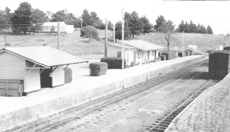
The line on the right is the goods siding, and I have enlarged the gap between it and the passing loop. If you look at the image below and compare it with the Ken Ames photograph a the top of the blog, the spacing looks more correct now (it's subtle but prototypical, and definitely noticeable).

That Ken Ames photograph is very valuable. The more I study it (each time I open the blog), the more stuff I notice. For example, the pots in front of the station building, the signal pulley posts in front of the platform, etc. Perhaps this is a good reason to put a picture like this in the dunny or on the fridge so that I see new details several times a day!
Tonight I have been wiring up the rails. I am sure I have used an unconventional process, necessary because all the track for this module has ended-up as a soldered, one-piece assembly. Anyway, it seems to be working so far. For those interested, here is the process I have used:
1. Determine the position of the track on the baseboard, paying careful attention to the proximity to the platform (rollingstock should be prototypically close without collision)
2. Mark the baseboard with the position of the rail where "droppers" are required. Droppers are the feeds to the rail from beneath the base-board
3. Mark the rail to coincide with the markings on the baseboard, so that later the droppers will line up with the holes in the baseboard.
4. Drill holes in the baseboard for the droppers, coinciding with the marks made in step 2.
5. Solder insulated multistrand wire to the underside of the rail (so that it cannot easily be seen from above). I have used wire with red insulation for one rail and black insulation for the other. Areas which are to have switched polarity have mauve insulation (for example, the point frogs).
6. Place the rail assembly in position and feed the wires (each of which are about 15cm long) through their corresponding hole.
At this stage, I now have the situation where the rail assembly is sitting about 50mm above the baseboard, supported by the droppers. This makes the thing look a bit like a rollercoaster; rails in mid-air! Very cool. I will take some photos to show you the Kingsvale "Wild Mouse".
Tomorrow I can pull the rail down to the baseboard, finish detailing the points, install point motors and DCC and run a bit of a test. Then I can paint the rail, put sleepers in place and ballast.
Tomorrow, it's the Epping exhibition - looking forward to that! A new AJRM will be a bonus.
Until next time
James.
No comments:
Post a Comment